PWM - Pulse Width Modulation.
The basics about PWM can be read here
Why PWM??
Suppose you have a motor with a certain torque and RPM, and you want to change the RPM. This can be done easily by reducing the voltage supplied, but due to this even the torque of the motor reduces. So, how to control the RPM of the motor without compromising on torque ???
The answer is PWM - Pulse Width Modulation
However PWM can be used in a lot other application too like controlling the brightness of an LED, generating various sound with a buzzer, etc.,
How to generate a PWM??
PWM uses a square wave whose duty cycle is modulated resulting in variation of the average value of the wave form.
See the following two pictures, here t is the duty cycle.
In the first picture the signal is high for 75% of the duty cycle leading to a higher average value than the second one which is high for only 25% of the duty cycle.


Here is a small LED dimmer application using PWM
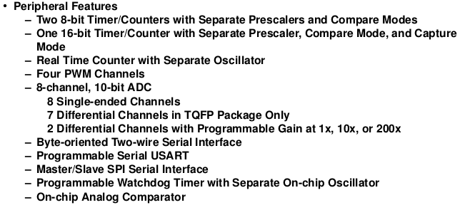
As PWM is based on timing, obviously a timer should be used. You can see from the ATMEGA 32 datasheet that ATMEGA 32 has four PWM channels any one of the channels can be used to generate the PWM output.
While using TIMER 0 to generate PWM the PB3 pin of the Atmega32 is to be used as the output for the PWM signal, the OC0 pin.
- Connect the output to LED.
- Set the PB3 pin high as the timer starts
- PB3 pin is cleared as the value of TCNT0 becomes equal to OCR0. This is the compare match.
- As TCNT0 reaches maximum value the TIMER 0 overflows. At the instance the PB3 pin is set to high.
Thus the PB3 pin remains High during TCNT0 = 0 and TCNT0<OCR0 and Low during TCNT0>OCR0 and TCNT0<255 ( as TCNT0 is single byte register 2^8 - 1 = 255 which is the max value). So by changing the value of OCR0 we can change the average value.
Here i use the Fast PWM mode to generate the signal
CODE:
#include<avr/io.h>So now the LED get brighter an then gets dull and cycle continues
#include<avr/interrupt.h>
int main(void)
{
DDRB = 0x08; //Use only PB3 as Output
PORTB = 0xF7;
OCR0 = 10; //Set Compare Value
TIMSK = _BV(1); //Enable compare match interrupt for Timer 0
TCCR0 = _BV(0)|_BV(1)|_BV(6)|_BV(3)|_BV(5); //Start Timer0 using 64 prescalar (bit 0,1),Fast PWM mode(bit 6,3),Clear OC0 pin on compare match (bit5)
sei(); //enable Global Interrupts
while(1)
{
asm("nop");
}
return 0;
}
SIGNAL(SIG_OUTPUT_COMPARE0)
{
OCR0++
if(OCR0 >= 250)
{
OCRO = 10;
}
}
No comments :
Post a Comment